


S-Series: Guitar Build Guide
by Richard Norton 17/12/2025
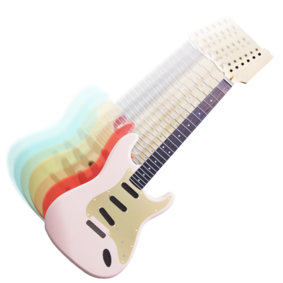
Welcome to the Guitar Anatomy S-Series Build Guide. This is a detailed walk through for building a Strat-style guitar using professional-quality parts. This tutorial is designed to help you assemble one of our Guitar Anatomy S-Series DIY kits, which include all required hardware, electronics and adjustment tools. The instructions apply to all Stratocaster-style and Strat-compatible builds, even if you are combining parts from different manufacturers.
Whether you’re building a Strat-style guitar, creating a custom partscaster, or upgrading an existing Stratocaster, this guide covers the full process from assembly to setup.
This guide focuses on assembly, wiring and setup, with no woodworking required (e.g carving your own body & neck)
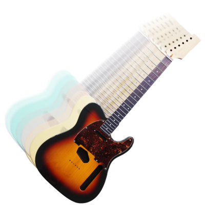
If you are building a Tele or Tele-style guitar, please see our dedicated Telecaster Build Guide.
Tools Required
Essential Tools
- Phillips screwdrivers: PH0, PH1, PH2
- Drill and bits: 5 mm, 2 mm, 3 mm and 10 mm (for 2-point trem)
- 11 mm & 12mm spanner or socket
- Soldering iron & solder
- Ruler or tape measure
- Masking tape
- Pencil / bradawl
- Wire strippers
- Sandpaper (various, for small fit adjustments) – see our dedicated setup guide
Optional
- String winder
- Heat shrink tubing
- Cable ties
- Multimeter
- Small pliers / tweezers
- Rubber mallet
Setup Tools
- Nut files
- Tuner
- Feeler gauges
- All required Allen keys (included with GA kits)
Parts Checklist
(If using a Guitar Anatomy kit, all parts are included.)
Major Components
- Strat body (SSS, HSS etc)
- Neck
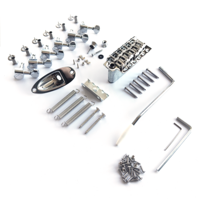
Hardware
- 6-screw vintage tremolo, 2-point modern tremolo or hardtail
- Neck plate + screws
- Pickguard
- Backplate (optional)
- Tremolo block, claw & 2 screws
- Tremolo springs (3–5)
- Tuners (6 inline)
- String tree(s)
- Strap buttons + screws
- Jack plate + output jack
Electronics
- GA wiring kit (pots, switch, wire, cap)
- Pickups
- Knobs
- Solder & wire
Fittings
- Pickguard screws (11)
- Backplate screws (6)
- Bridge screws (6, vintage) or 2 anchor posts
- Claw screws (2)
- Tuner screws (6)
- String tree screw(s)
Shaping the Headstock (All GA Kits)
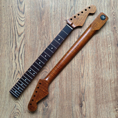
All Guitar Anatomy build kits come with an unshaped half-paddle headstock, giving you the freedom to create your own design. In this guide we will not cover the full cutting and shaping process, but shaping a headstock is much easier than most beginners expect.
Before cutting your headstock, we strongly recommend doing a quick dry fit of your neck, body, tuners and bridge. This ensures everything lines up correctly before you commit to your final headstock outline.
Once you’re ready to shape your design, here are some resources we recommend for clear guidance:
- Long-time collaborator Michael Largerstedt guides you through shaping and cutting your own design from a GA neck.
- Long-time collaborator MixwithABD guides you through shaping and cutting your own design from a GA neck.
Take your time when marking and cutting, and sand the edges smooth before continuing with assembly. Once shaped, the rest of this build guide applies exactly the same as normal.
If you would like further advice on this step, get in touch with the GA team.
STEP 1 — BEFORE YOU BEGIN
1. Prepare Workspace
- Use a stable, well-lit bench.
- Lay down a soft cloth or pad to protect your components.
- Organise tools and small parts.
2. Dry Fit Check
Before drilling or soldering:
- Ensure the neck fits snugly into the pocket. (Different brands can have slight compatibility differences, so you may need minor adjustments, but GA kits are designed to fit perfectly together.) (Figure 1A)
- Check pickguard routs and bridge position. (Figure 1A)
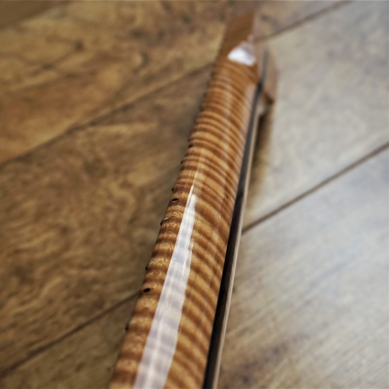
Confirm the 25.5″ scale length (nut → saddles ≈ 25.5″). (Figure 1B) *Scale length is the vibrating length of the string, measured from the nut to where it meets the saddle. Frets are spaced according to this distance, so the bridge needs to sit where the high-E saddle ends up roughly 25.5″ from the nut. Saddles will adjust slightly back for the thicker strings, but the high-E side should be close to that exact length for correct intonation.
💡 Tip: Small bowls help prevent losing screws.

Figure 1A

Figure 1B
You’re ready to begin.
STEP 2 — NECK & HARDWARE PREPARATION
A. Fit the Tuners
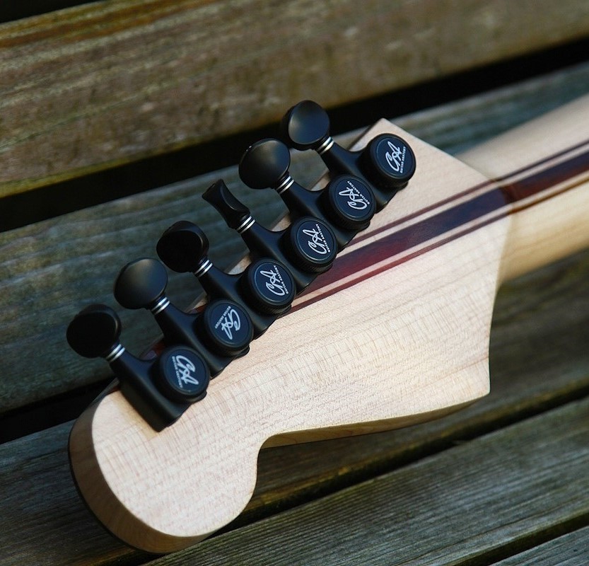
- Insert each tuner from the back of the headstock (Figure 2A)
- Add washer + threaded bushing from the front; finger-tight.
- Align tuners using a ruler (Figure 2B).
- Mark locator screw holes.
- Remove tuners, drill 1.5 mm pilot holes (to the depth of the screw).
💡 Tip: Add masking tape around the drill bit to act as a depth guide so you drill the right depth.
- Refit tuners and tighten bushings with a spanner or socket.
- Install locator screws.

Figure 2A

Figure 2B
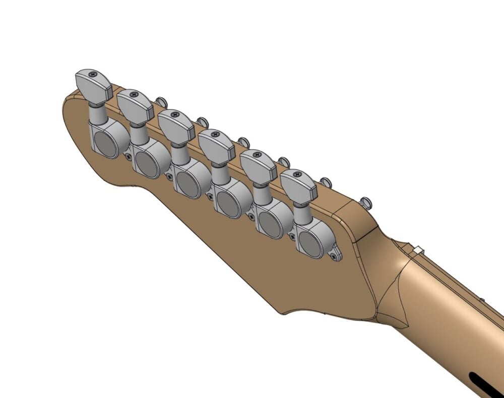
Figure 2C
B. Fit the Strap Buttons
-
- Position buttons: Lower bout and Upper horn
- Mark holes.
- Drill 1.5 mm × 6–8 mm.
- Fit button + felt washer (Figure 2D & 2E)
- Tighten screws snugly.

Figure 2D

Figure 2E
C. Neck, Body & Bridge Alignment
- Seat the neck in the pocket. (Figure 2F)
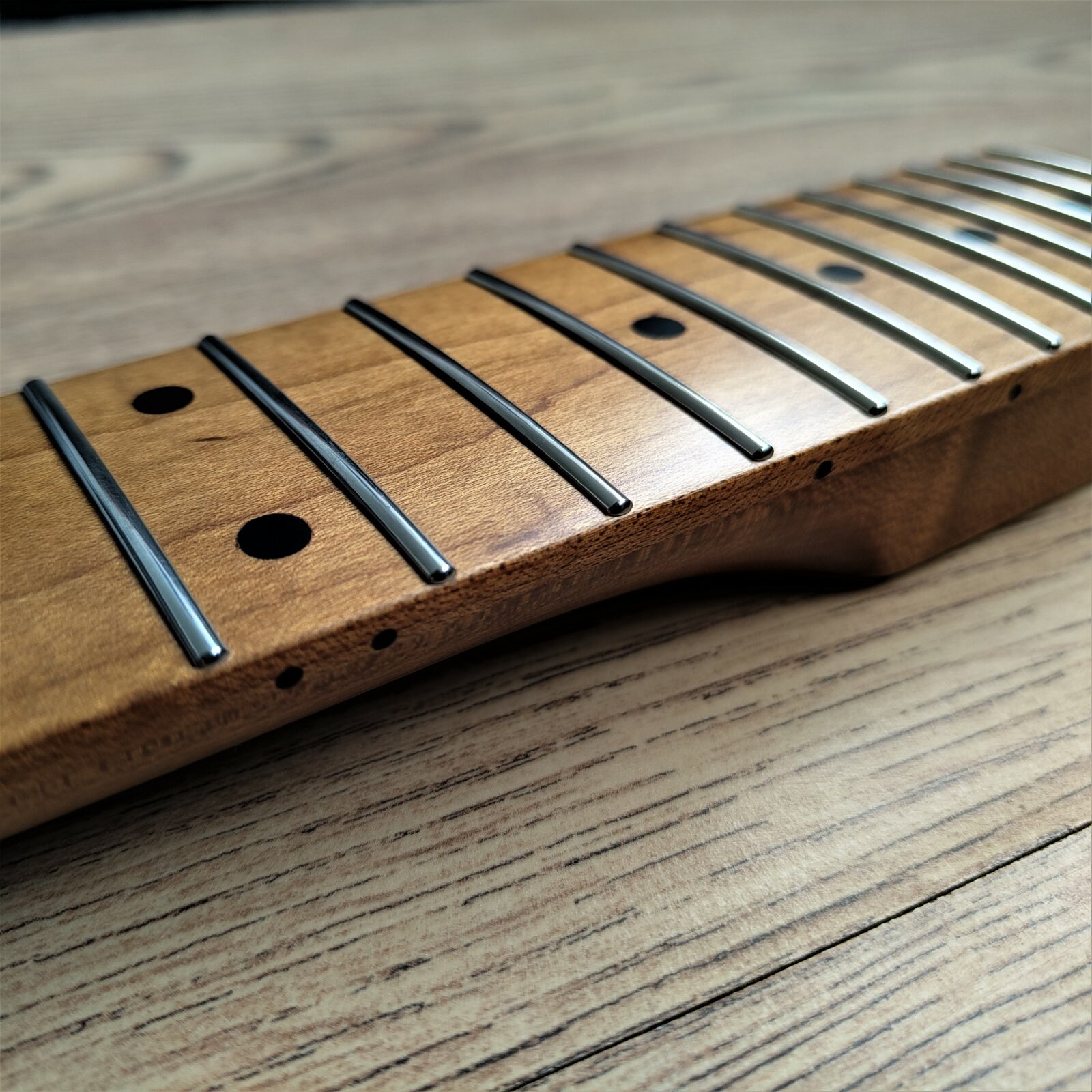
*Note: Some Stratocaster necks have 21 frets, while others have 22. A 22 fret neck usually has a small fretboard overhang that sits above the body, as shown in the figure. A 21 fret neck will stop at the heel with no overhang. Both types fit the same neck pocket, so either is correct. - Place bridge plate roughly in position.
- Fit low E and high e strings loosely (Figure 2H). (Can use twine)
- Ensure strings run evenly along both fretboard edges. (Figure 2G)
- Check scale length: (Figure 2H)
- 12th fret → saddle ≈ 75″ (324 mm) (Remember, you do have some adjustment in your saddles, so don’t expect it to be exact)
- Adjust neck position until alignment is perfect. Aim for an even gap between each outer string and the edge of the fretboard on both sides. *This prevents the strings sitting too close to the edge, which can cause slipping off the fret during playing, and ensures comfortable playing feel across all frets.
- Once aligned, mark the bridge position.
💡 Tip: Add masking tape around the neck joint to hold the neck firmly in place while you mark the bridge location.

Figure 2F
Figure 2G
D. Drill Bridge Mounting Holes
Now we have our alignment, we will secure the bridge. Remove the strings from the neck & bridge and keep them to one side.
Vintage 6-Screw Trem
- Mark 6 holes through bridge plate.
- Drill 2 mm × 12–14 mm deep.
- Keep drill vertical.
- Fit Bridge As shown in Figure 2I. *Note: When fitting a 6-point tremolo, the screws shouldn’t be fully tightened down, we need to leave a little bit of play if we want the tremolo to function. Leave around 0.5mm to 1mm gap between the underside of the screw heads and the top surface of the bridge plate. This can be adjusted later. As a general rule of thumb, we can tighten the screws down and then back each screw out roughly a quarter turn.
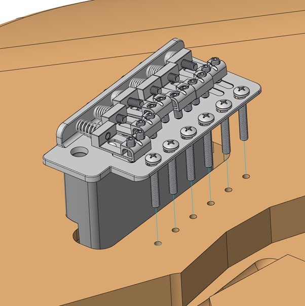
Figure 2H
Modern 2-Point Trem
- Mark 2 post holes.
- Drill 10 mm holes to the correct depth (use bushing as guide).
- Tap bushings flush using rubber mallet.
Fit Bridge as Shown in Figure 2I
Hardtail
- Same alignment & fit process; no tremolo components.
STEP 3 — BRIDGE & TREMOLO INSTALLATION
A. Install Tremolo Claw
- Position claw with hooks facing the bridge (Figure 3A).
- Centre it with the tremolo block.
- Mark the holes and drill 2 mm × ~15–18 mm deep.
- Fit claw screws. Only tighten the screws a few turns, we want to fully tension the tremolo once we hook the springs onto the claw. (Figure 3A)
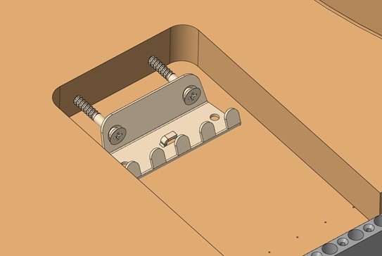
Figure 3A
B. Fit Springs
- Hook springs between claw and block (figure 3B)
- Use 3 springs for standard feel, 4 for a little more tension, and 5 for the maximum tension (This can be adjusted later)
- Tighten claw screws until the springs are taut.
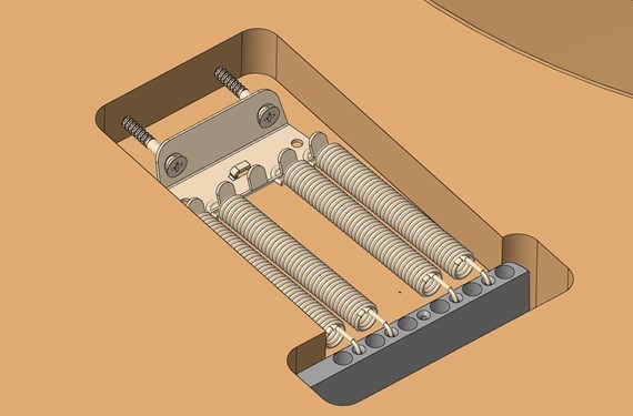
Figure 3B
C. Preliminary Tremolo Setup
- Bridge should rest flat or slightly angled up (slight gap between bridge and body at the rear edge)
- Adjust claw screws evenly.
💡 Tip: Final balancing happens after stringing.
OPTIONAL — SHIELDING
- Shielding is optional, but highly recommended. It helps reduce electrical hum, especially with single-coil pickups—and usually results in a cleaner, quieter guitar. It adds a few minutes to the build, but the improvement is worth it.
-
Materials
- Copper foil tape or shielding paint.
-
Method
- Line cavities with overlapping foil, or paint 2–3 coats.
- Shield underside of pickguard.
- Ensure body and pickguard shielding make contact.
- Use multimeter to confirm continuity (Optional)

Figure 3C
STEP 4 — ELECTRONICS & PICKGUARD ASSEMBLY
A. Load the Pickguard
- Fit pickups from back; mount with screws + springs. (Figure 4A)
- Install pots and switch; secure with nuts/washers. Tighten pot nut with an 11mm spanner or socket. (Figure 4B)
- Ensure smooth operation of controls, and fully tightened.
- Finally, push fit your knobs & switch tip onto the Pots & switch (Figure 4C)
Note: Pot shafts come in different spline counts and sizes. CTS pots are imperial sized, while Alpha and many other brands use metric shafts. Knobs must match the pot type to fit correctly, and mixing metric and imperial parts is a common mistake. All pots and knobs supplied in Guitar Anatomy kits are fully compatible, so everything will fit together without issues.
💡 Tip: If you need to adjust your pot heights, you can use an extra nut and washer underneath the pickguard.

Figure 4A

Figure 4B
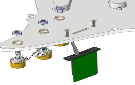
Figure 4C

Figure 4D
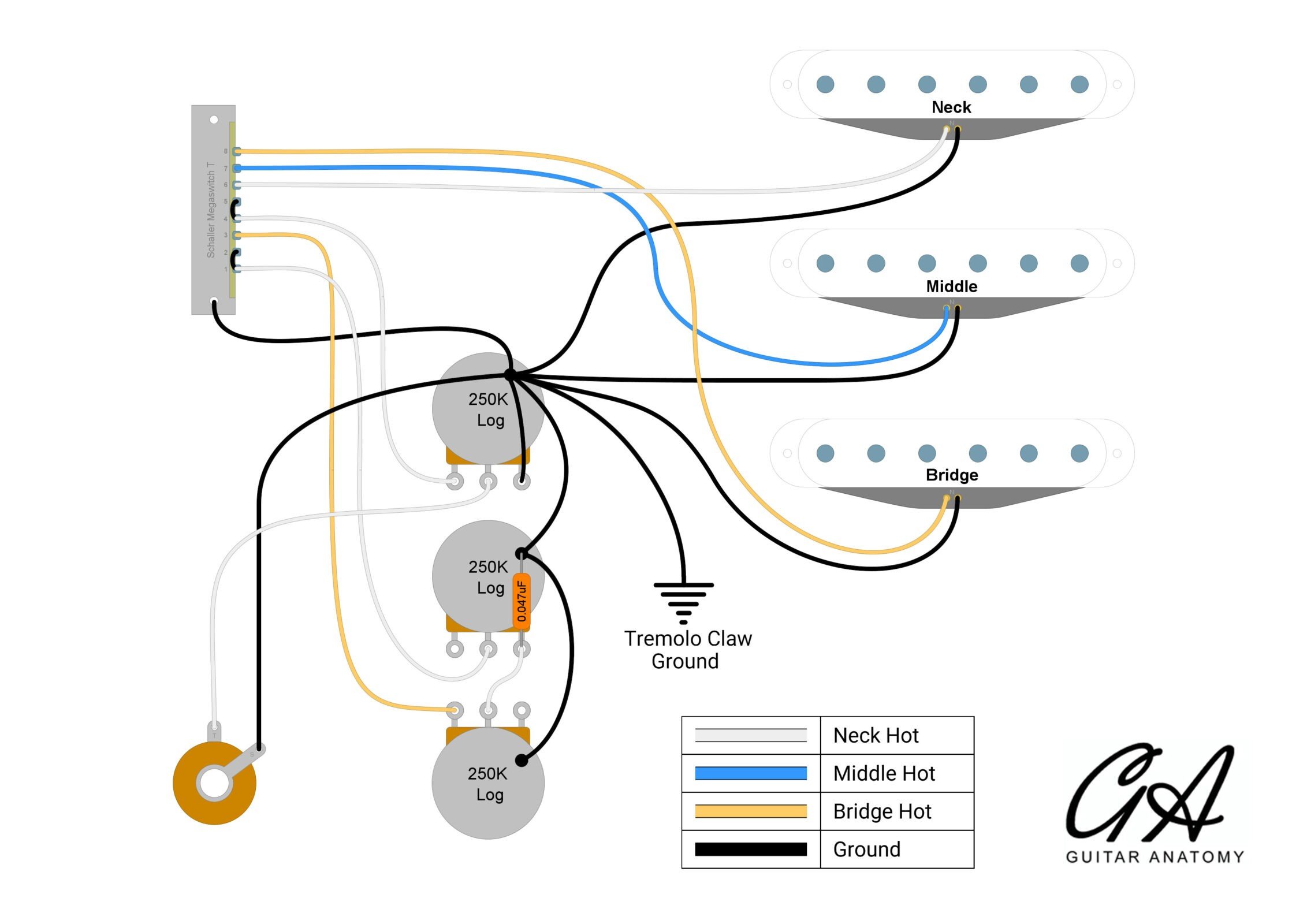
B. Wiring
Follow your Guitar Anatomy wiring diagram. Below shows our Standard Strat Wiring diagram. You can also find all of our diagrams HERE
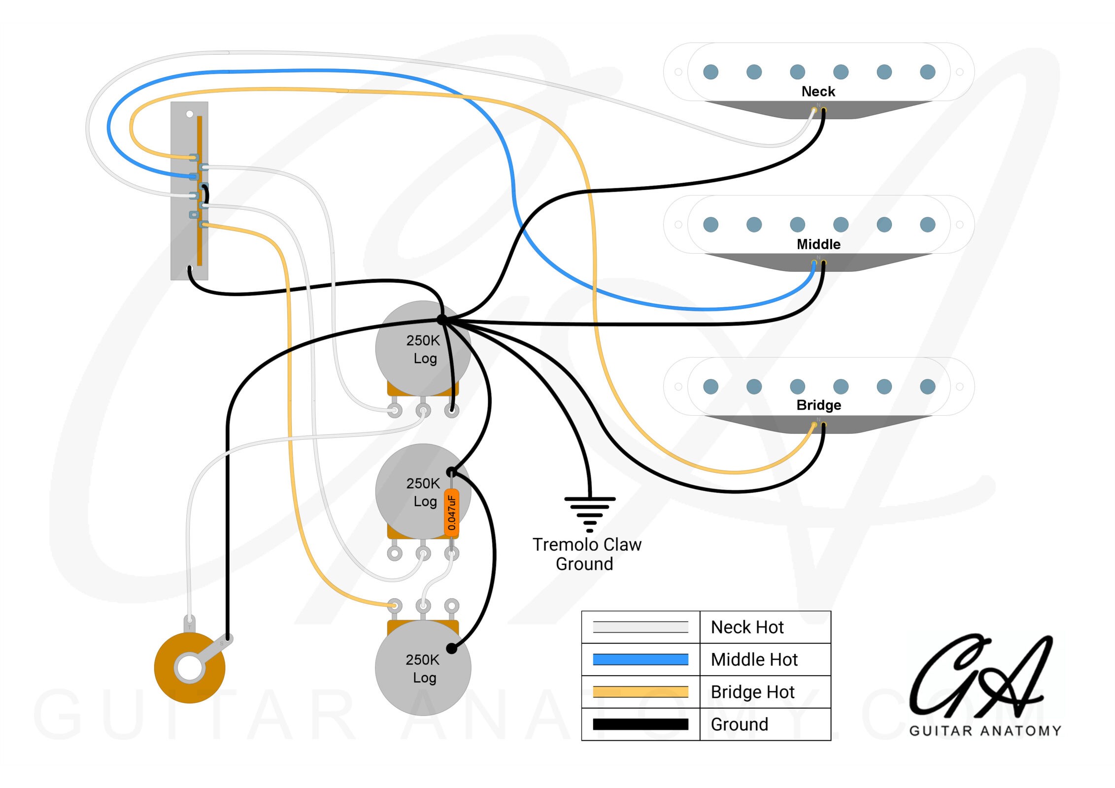
Figure 4E
Soldering Basics
Before starting:
- Work in a well-ventilated space.
- Wear eye protection and keep the iron in a stand.
- Remember: the tip is extremely hot and stays hot after turning off (even when powered off).
How to Make a Good Joint
- Heat the part (lug/tab), not the solder.
Let the metal get hot first. - Feed solder once warm.
It should flow smoothly onto the surface. - Let it cool naturally.
Don’t move the wire until the solder sets.
💡 Tip: Good joints look smooth and shiny, not dull or cracked.
Grounding to Pot Casing
- Lightly scratch the casing to remove coating.
- Tin the pot and tin the wire
- Bring them together and heat for 2–3 seconds so the solder melts together.
⚠ Avoid prolonged heating. Too much heat can damage the pot internally.
Tidy Wiring (Optional)
- Use heat-shrink tubing over exposed joins.
- Keep wires neat with ties or small clips.
- Leave slight slack to prevent strain.
Safety Reminders
✔ Ventilate—avoid breathing fumes directly
✔ Wear eye protection
✔ Keep hot tools away from cables and surfaces
✔ Wash hands after soldering
STEP 5 — INSTALLING THE OUTPUT JACK
A. Assemble Jack on Plate
- Insert the jack into the mounting plate (Figure 6A).
- Tighten the securing nut with a 12 mm spanner or socket—firm, not overtight.
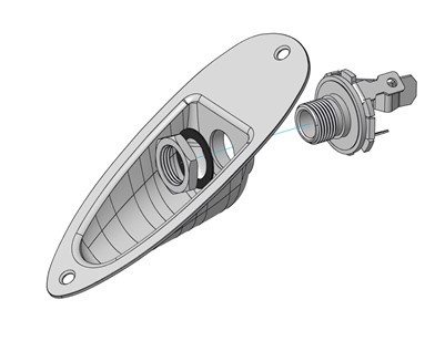
Figure 5A
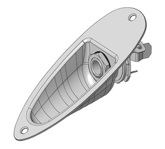
Figure 5B
B. Route Pickup Wires
- Guide the hot (white) and ground (black) wires from the underside of the pickguard through the control cavity and into the jack cavity.
- Use a small screwdriver or tweezers if access is tight.
- Make sure wires sit loosely and are not under tension when the pickguard is in position (flat against the body).
💡 Tip: Keep wires away from sharp edges inside cavities to prevent rubbing through the insulation.
C. Solder Connections (Figure 6B)
• Solder the hot wire → inner lug (signal connection).
• Solder the ground wire → outer lug (sleeve connection).
• Allow both joints to cool naturally.
💡 Tip: It helps to tin both the lug and the wire first—this makes the final join quicker and cleaner.
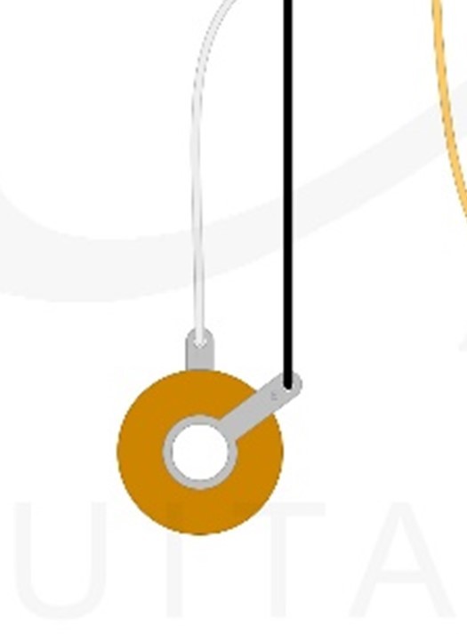
Figure 5C
D. Install Jack Plate
- Position the plate on the side of the body (Figure 6C).
- Screw the plate into place securely.
👉 If the body is painted, drill 1.5 mm pilot holes first.
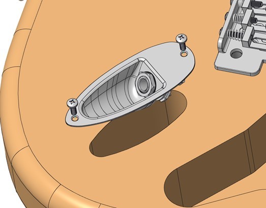
Figure 5D
Function Check
- Plug in a guitar cable—it should click in firmly and feel secure.
- Connect to an amp.
- Gently tap the pickup pole pieces (the small round metal dots on top of each pickup) with a screwdriver.
- You should hear a clear tapping sound for whichever pickup is selected.
- Switch pickup positions and repeat—each pickup should respond.
- Touch the bridge or strings; a slight hum should reduce—this shows the ground connection is good.
If it’s not working:
- No sound at all → check that both wires are soldered correctly to the jack lugs.
- Only noise or crackling → reflow the solder joints.
- One pickup works but another doesn’t → check wiring to the selector switch.
- No change when you touch metal parts → the ground wire may not be connected properly.
STEP 6 — Fitting The Neck
A. Check Fit
- Ensure pocket is clean.
- Seat neck snugly (no force).
B. Align the Neck
- Fit E and e strings lightly.
- Adjust neck until both strings are evenly spaced along fretboard edges (Figure 5A).
Figure 6A
C. Mark & Drill Pilot Holes
- With neck in place, mark screw holes (make an indentation) through the body clearance holes. (You can use the neck screws for this, a pencil, or bradawl (Figure 5B)
- Remove neck.
- Insert a neck screw through the body with neck plate installed.
- Measure screw protrusion — this is your drill depth.
- Mark drill bit with masking tape.
- Drill 3 mm pilot holes to measured screw depth.
- Clean debris.
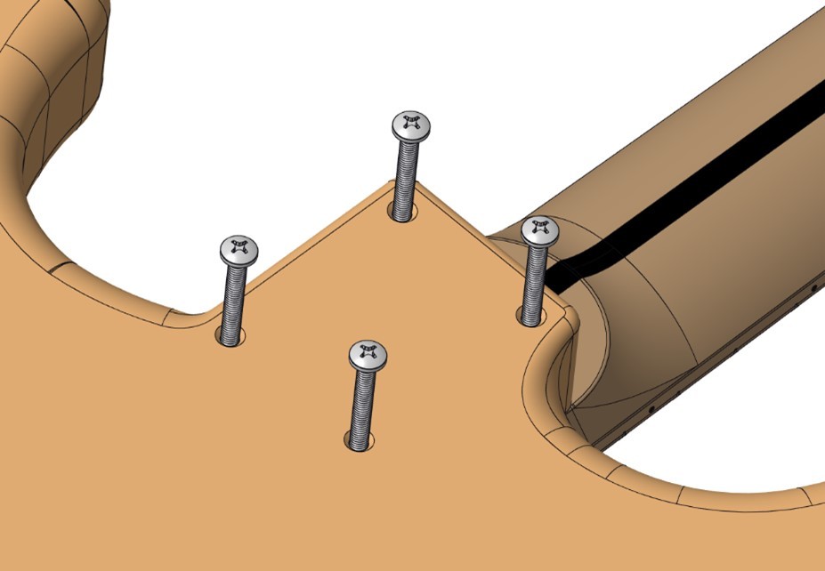
Figure 6B
D. Attach the Neck
- Position neck plate + (gasket) (Optional)
- Tighten screws in cross-pattern; firm, not overtight (Figure 5C)
💡 Tip: Don’t fully tighten one screw before starting the others.
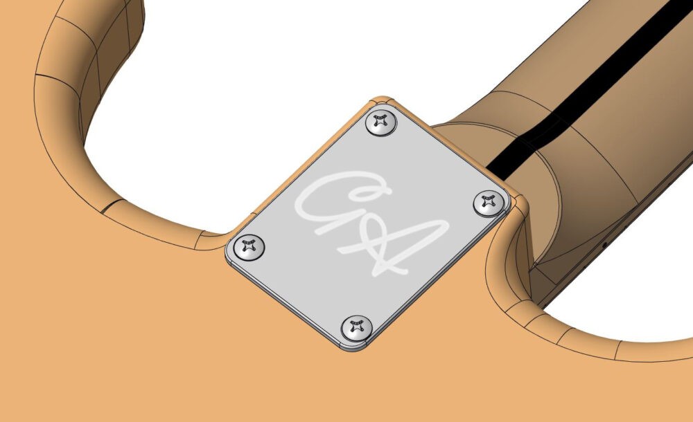
Figure 6A
E. Final Check
-
- Confirm outer strings still align correctly.
- Adjust if needed.
STEP 7 — Fitting The PICKGUARD
PICKGUARD
A. Prepare Wiring
- Tuck wires neatly into cavity.
- Ensure no pinching.
B. Mark & Drill Pilot Holes
- Position and align the pickguard.
- Mark the screw hole locations.
Tip: You can either hold the pickguard by hand or use masking tape to keep it in place while marking. - Drill pilot holes using a 1.5 mm bit, around 6–8 mm deep.
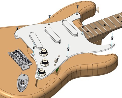
Figure 7A
C. Install Pickguard & Backplate (Figure 7A & 7B)
- Start all screws first, then tighten evenly.
Do NOT overtighten.
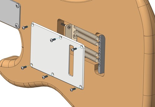
Figure 7B
D. Another Quick Function Quick Check
- Plug into amp, tap pickups.
- Confirm all selector positions work.
STEP 8 — String the Guitar & Install the String Tree
A. String the Guitar
- Feed each string from the bridge up to the correct tuner post.
• Wind the strings so they wrap neatly downward on the post (2–3 turns for thin strings, 1–2 for thick ones).
• Tune to pitch.
• Gently stretch each string and re-tune.
💡TIP: Once stretched and re-tuned, the guitar will hold tuning better.
B. Install String Tree (Figure 8A)
- With the strings now fitted and under light tension, position the string tree so it gives the correct downward pressure on the top two strings. Note* This is often in line with the A string tuner post, or thereabouts
• Mark the screw location and drill a small 1.5 mm pilot hole.
• Fit the string tree and tighten gently so it sits flat.
💡 TIP: Installing the string tree after stringing lets you use the actual string lines to place it accurately and avoid pulling the strings sideways.

Figure 8A
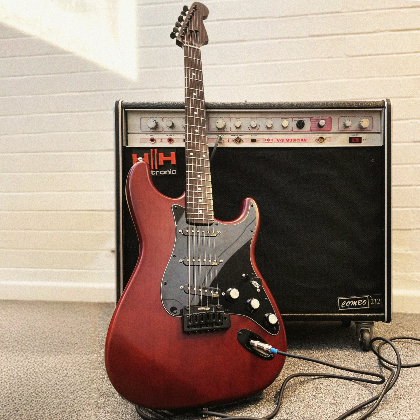
COMPLETED BUILD
Your Stratocaster is now assembled, wired and playable. At this stage your guitar is fully assembled, but the action and playing feel will depend on your setup. You can now adjust string height, tremolo balance, intonation and pickup height to suit your preference. If you are unsure, you can either take your guitar to a local luthier for a professional setup, or follow our full setup guides HERE, which walk you through every step including action targets, truss rod adjustments, and intonation settings.